


We meet Tuesday evenings 19:45 for 20:00, Thursday mornings 10:00 and Sundays 14:00. Tuesdays and Sundays are hybrid in person and Zoom meetings (Join us in person or using zoom, code 867 3049 5863) Thursday mornings are exclusively in person, see schedule below or contact us for more details.
Event Information:
-
Advanced DSP and PIC (WARCPIC)
Using a PIC to build a programmable Digital Signal Processor
A club project designed by Dave Roberts, G8KBB, and George Fare, G3OGQ.
Background
Those with knowledge of our membership will appreciate that we have three very talented members who have developed the CDG2000 advanced transceiver. The Mark 2 design which has full DSP is at present under design and will be available in the future.
The team are also working on computer controlled radio designs. This project gives club members the ability to experiment with programmable DSP and variants on the design may also be used in other designs.
Hardware
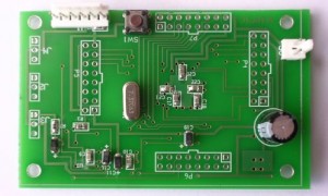 Club members will start by building two circuit boards. The WARCPIC main board is based on dsPIC30 family from Microchip which is a state of the art PIC chip designed for signal processing. More details about this can be found at Microchip's website. The chip is mounted on a small PCB with supporting components and interfaces to control circuitry and to the debugger board. The signal interface is an SI3000 audio Codec IC which handles the audio signals at line level.
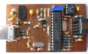
The PIC chip is programmed via the debugger board which is the second piece of hardware. It has the ability to perform three functions, it can step the WARCPIC board through a program to debug it, it can program the WARCPIC board and it acts as an interface to a PC to download programs via an on board FT232 USB interface chip.
Software
It is certainly true to say that Software will form the main part of this project and that program development will take place in varied facets of filter and circuitry control. To this end there are several pieces of software which will be installed on member's PCs and of course the eventual product will be the code running on the dsPIC30f.
Software includes Digital Filter Designer from digitalfilter.com which is used to design filter parameters prior to coding.
The MPLAB integrated development environment (IDE) is used for writing, compiling and possibly debugging the code.
Before this can connect to the ICD board a bootstrap code needs to be loaded, the easiest way to do this is via a PIC programmer either stand alone or fitted on a laptop.
If you do not have access to a programmer, a quick and dirty way to program is using a PIC Programming Cable described by Lothar Stolz. This is used in conjunction with a free program called IC-Prog courtesy of Bonny Gijzen. IC-prog can be installed quite easily onto the PC once the latest version is downloaded, The PIC16F876 is selected from a drop down list and the hex file BL010101.hex is to be found on the Making CD under ICD2.
If you have not got access to a PIC programmer or breadboard it should be possible to program it in situ on the ICD2 board. It would be necessary to disable the transistor by shorting its base and emitter so that it does not provide a low impedance path across the incoming data. The serial cable can then be connected as per Stolz diagram.
MPLAB connects to the ICD2 debugger board and works in conjunction with another PIC chip, the PIC16F876, this communicates with the PC program via the USB interface, the drivers for which should be installed on the PC before connection so that the device is recognised correctly.
If the device is connected to the PC without first installing the drivers it may have to be removed using device manager before the system can be setup correctly.
The debugger device can receive power from either the PC via the USB port or an independent power supply connected to the WARCPIC board. Damage may occur to a PC or other parts of the system if more than one supply is connected at the same time. PC's can only suppply 0.5 amps via the USB port interface and this should be considered if several USB devices which require power are connected to a PC. USB hubs are available which work off a separate power source and these may be more suitable for some users.
Setting Up The MPLAB IDE software
NB a bootstrap program should have been loaded onto the PIC16F876 chip from an PIC programmer or serial lead before this stage is reached.
Once the software has been installed it is time to get it to talk to the debugger board, this is done via the USB cable and windows driver which are configured in Windows as the lowest COM Port device available. At this stage it is also worth mentioning that it will not work if the COM Port buffer size is not set to minimum. To do this in Windows XP follow this procedure after the driver has been installed and the USB lead connected.
Control Panel | System | Hardware | Device Manager |
If all is well it should be possible to look under Ports COM and LPT to see the COM port added by the USB controller, if there are several COM ports disconnect the USB lead and see which one disappears, if all is well it should reappear when the cable is reinserted. If it is COM 1 then all is well but if there are other COM Ports either emulated or physically installed hardware then the number of the COM port for this device may need changing to the lowest available number. To make this change
Right Click For Properties | Port Settings | Advanced | Select Port Number |
Port number selected should be changed if necessary to lowest available. Before clicking on OK also change the transmit and receive data rates to 64 or it will not work. Close the properties and then re-examine to make sure the settings are correct.
Device manager is now closed prior to running the program.
Start by setting the following parameters.
1. Select the device that we will be debugging
Configure | Select Device | DSPIC30F6012A known as the target device.
2. Select the tool we will be using
Debugger | Select Tool | MPLAB ICD2
3. Set up the tool using the Wizard using the COM port which was enabled for the USB device in device manager, on some computers it maybe best to always use the same USB port to keep the COM port configuration. The baud rate defaulted to 19200 but this appears to work. Tick the box to automatically download the operating system on the 3rd step
4. If all is well it should be possible to connect to the debugger, on successful connection a software program will load down this is required on the first operation. If an error message occurs to say that test failed but it appear to have connected it may be the voltage is out of range in any case it should be checked and adjusted.
Debugger | Connect
Debugger| Settings | Power Click the refresh and adjust the pot to 13 - 13.2 volts
5 Test
Debugger | Settings | Status | Run Self Test Note any failures here it should all pass.
Output
 ICDWarn0034: Please ensure that your system's serial FIFO buffers are disabled.

Connecting to MPLAB ICD 2

...Connected

ICDWarn0030: MPLAB ICD2 is about to download a new operating system. If MPLAB IDE is just starting, it will appear to "hang" at the splash screen. Please be patient. MPLAB IDE will finish it's intialization after the OS is downloaded. (Note: You may wish to select to ignore this warning in the future.)

Downloading Operating System

Connecting to MPLAB ICD 2

...Connected
The Target Board
In order to check that the target DSPIC30F6012A is being recognised follow this procedure.
1. Connect the target board with a short length of ribbon cable.
2. Connect the USB cable
3. Repeat the above but this time you should get a message to say the DSPIC30F6012A is found
Output:
 ICDWarn0034: Please ensure that your system's serial FIFO buffers are disabled.

Connecting to MPLAB ICD 2

...Connected

Setting Vdd source to target

Target Device dsPIC30F6012A found, revision = Rev 0x1002

...Reading ICD Product ID

Running ICD Self Test

...Passed

MPLAB ICD 2 Ready
One thing I found irritating with this sytem is that the number of the COM Port continually needed resetting on my machine, if it does not reconnect check this. The next step is actually do some programming.Putting your first program on WARCPIC
Once the target device has been reported as found the next step is to put a program on it which will test this device and also the ST3000 chip which takes data in which is output from a program running on the dsPIC30F6012A and either modifies the audio input or produces an audio output. In this example we will use a test program which was provided on the CD and was originally downloaded from Moe Wheatley's website (AE4JY) but has been modified for our purposes by Dave, G8KBB. The original software supported a more complex version which offered menu controllable options. The WARCPIC board is much simpler and in its basic form does not offer these options. Here are the steps you need to follow to get the WARCPIC programmed.
1. From the CD provided by Dave, G8KBB, copy the folder with all files cddrive\moetronix\dspdemosource modified for WARC to the hard drive of your computer possibly as a sub folder to your main WARCPIC folder. The destination of this folder is not critical but make sure you can find it again later.
2. The MPLAB IDE Version 7 should already have been installed from the CD and also the C30 compiler requires installing if not previously installed, this is on the CD at cddrive\microchip\C30 compiler\dspdemosource\MPLAB_C30_V2_O2Student-edition.exe Double click the file and follow the install dialogue. This program appears to operate as a plugin and works within the IDE once installed.
3. Connect the WARCPIC and debugger boards together using a short piece of ribbon cable, and connect the debugger board to the PC using a USB cable.
4. Start the Microchip IDE program.
5. Open the project you copied from disc Project | Open | DSPdemo.mcp
6. You will now have an Output window and a window called DSPdemo.mcw which looks like a small version of Windows Explorer with all the files in it for this project. There are several sorts of files which make up a programming project, you will see files ending in .h which are header file these contain basic function definitions which other programs build on. Files ending in .o are object files, these are intermediary compiled files which will be used to create the final hexadecimal code which will be transferred to the PIC.
7. The program source is kept in a file with a .c suffix. In this example we will make a small change to the main.c file so that the compiled code will produce an output tone from the board which is proof that all is working. The file can be edited by double clicking on it in the project window. Scroll down the file until the section MAIN appears. In this section
 InputSrc = SRC_CODEC;

CurrentInScale = 20000;

DspProc = DSP_LPFIR;

CurrentMenu = -1;

InitProcDSP( DspProc );

//LMSmu = 30;
Edit the above till you haveInputSrc = SRC_SINE;
CurrentInScale = 20000; // This value changes the output volume you can try changing it to 200.
DspProc = DSP_NONE;
CurrentMenu = -1;
InitProcDSP( DspProc );
//LMSmu = 30;
You have now changed the program to produce a sine wave output audible in a pair of headphones. Save the amended file by closing its window and Saving when prompted. Thanks to Paul, G1DVA, for this amendment.8. Compile the amended program by running Project | Build All.
The last few lines of the output should appear thus error messages about the licence may be disregarded.
 Executing: "C:\Program Files\Microchip\MPLAB C30\bin\pic30-bin2hex.exe" "DSPDemo.cof"

Loaded D:\My Documents\clup-project\dspdemosource modified for warc\DSPDemo.cof.

BUILD SUCCEEDED: Sat Feb 17 14:20:55 2007
9. Connect to the board by first Selecting the programmer, Programmer | Select Programmer | MPLABICD2
If it does not connect try Programmer | Connect;
and if necessary check Programmer | Settings | Communication to ensure the correct COM port is selected.You should now see this output
 MPLAB ICD 2 Ready

ICDWarn0034:

Please ensure that your system's serial FIFO buffers are disabled.

Connecting to MPLAB ICD 2...Connected

Setting Vdd source to target

Target Device dsPIC30F6012A found, revision = Rev 0x1002...

Reading ICD Product ID

Running ICD Self Test...

Passed

MPLAB ICD 2 Ready
10. Next program the chip Programmer | ProgramIf successful the output will be as below:
 Programming Target......

Validating configuration fields...

Erasing Part...

Programming Programming Executive...

Verifying Programming Executive...

Programming Program Memory (0x0 - 0x283F)

Verifying......Program Memory...Verify Succeeded...

Programming Configuration Bits..

Config Memory

Verifying configuration memory......

Programming succeeded17-Feb-2007, 14:24:04

MPLAB ICD 2 Ready
11. Connect your headphones to the output of SI3000 / J313. Whilst listening disconnect the programmer, Programmer | Select Programmer | None, if all is well the generated tone will be heard.
You may prefer to disconnect the WARCPIC for this and power it separately from a 9 volt battery or other source, in any event at no time connect another power source if the computer USB is still connected.
A projects mail group has been set up to monitor progress. Members may subscripe to this group at http://mail.warc.org.uk/mailman/listinfo/projects_warc.org.uk
The club is indebted to G8KBB, G3OGQ and G3SBI for their work on this and the CDG2000 projects.
Commentary by Ian, M0BXR updated Feb 2007.

