We meet Tuesday evenings 19:45 for 20:00, Thursday mornings 10:00 and Sundays 14:00. Tuesdays and Sundays are hybrid in person and Zoom meetings (Join us in person or using zoom, code 867 3049 5863) Thursday mornings are exclusively in person, see schedule below or contact us for more details.
Event Information:
-
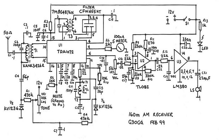
Millennium Project 160m AM Receiver
by George Fare, G3OGQ
General
This project is a top band (160m) superhet receiver with an IF of 455kHz. Construction is made easy by the use of a chip which includes an AGC controlled RF amplifier followed by a balanced mixer fed by an on-chip oscillator. An IF amplifier feeds a balanced full wave detector and an audio preamplifier gives sufficient power to drive an on board amplifier with an 8 ohm loudspeaker.
The single chip therefore does all the hard work. The sensitivity is better than 1 µV for 1 Watt output with a signal amplitude modulated to 85%.
There is plenty of room on the board but before starting work, please check the PCB. We have been having some difficulty with the photo resist boards for which we apologise, so check for broken tracks, wisps of copper between tracks etc. Broken tracks should be repaired by soldering a wire between pads - do not fit a 'splint'. Some boards will have traces of manual repair on them but should be OK. If you have a Mk 1 board (i.e. one that does not have Mk 2 written on it), fit a link to the pads of T2 as shown on the circuit diagram. (below C7) If you have been supplied with a board which still has the photo resist on then you can leave it on as this can be soldered through and it will keep the copper bright underneath.
The board will have to be drilled before you can start assembly. All holes are 0.8mm diameter except those for Veropins (lmm) and coil cans (1.3mm). Arrangements can be made for these to be drilled before the Tuesday meetings at the Club if you have not got a drill.
Check that you have got all the parts by comparing with the parts list. The only item not included is the S meter which should be bought at a rally for cheapness (or you can do without).
Construction

The PCB should be completed first. Fit the Veropins by pushing them in with a pair of pliers from the component side until a click is felt. Mount the resistors next, pushing them down on the board with the markings all in the same direction horizontally or vertically.
Solder the pins and resistors putting heat on the copper pad and the component lead at the same time. The joint should be nice and bright.
Fit the capacitors next making sure that the electrolytics are correctly polarised. The coils are the next things to be mounted and can only be fitted one way round.
Follow this with the filter, the varicap diode (with the markings facing into the board) and the ICs. Note that the LM380 has a lot of pins soldered to a large pad. This is a heat sink so don't neglect to solder all pins.
When all components are mounted, check them all to see that they are in the correct place and fitted the right way round.
Connections can now be made to the tuning potentiometer, loudspeaker, antenna socket and the phono socket which takes the transmit / receive wire from the transmitter. Don't forget to fit the 10k resistor across the phono socket. The on/off switch can be left until you have a case to fit the board into. Until you have finished aligning the receiver, you should solder a wire between the mute pin and ground. If the mute pin is left floating, the AF amplifier on the chip will not work.
Alignment and Testing
To align the receiver you will need a power supply giving 12V at about 100mA, a frequency counter, a signal generator, an output meter, a voltmeter, a waveform analyser, a spectrum analyser, a general coverage receiver, or, if you have not got any of these, you can use your transmitter and a voltmeter!
First, check with an ohmmeter between the supply lead and ground. The reading should be about 3000 Ohms or more. If not, check everything again - if you don't, it may cost you!
If the reading seems OK, then apply 12V, making sure of the polarity. If you connect the wrong way round, please apply for a new kit!. Turn the volume control to maximum. You should hear a fairly loud hiss in the loudspeaker. If not, check everything between the volume control and the loudspeaker, especially chips and electrolytics are connected the right way round.
The next step is to get the local oscillator (LO) working on the correct frequencies. The LO frequency must be set at the incoming frequency plus 455kHz. That is, at 1.800 MHz, the LO should be set at 2.255 MHz and at 2.000 MHz it should be 2.455 MHz. The best way to do this is to monitor the frequency at pin 10 of the 1072 chip (which has a 10k resistor going to ground) - marked TP on the circuit diagram. If you have not got a frequency counter, borrow the Club's one or alternatively, if you have a general coverage receiver, you Can connect pin 10 to the antenna socket of the receiver and tune it to the required frequency.
Having set up your monitor, turn the tuning pot (VR1) fully anti-clockwise. This is the point at which we would want to receive 1.800 MHz. Then, slowly adjust T2 until the required frequency (2.255 MHz) is shown by the counter or at a peak S meter reading on your receiver. Turn the tuning pot to maximum and check that the frequency is 2.455 MHz or more. You can calibrate the dial at this stage if you want to, although this is best left until you have fitted it into a case. Next adjust T3 for maximum noise in the loudspeaker or for maximum voltage at the S meter pin, using either an antenna resonant at 160 metres or with a 50 ohm dummy load and a signal generator. (The Club's generator is perfect for this). Lastly, tune T1 for maximum signal as shown at the S meter pin, but also tuning out any broadcast stations you may hear in the background. You will need patience for this but it can be done.
The receiver can now be mounted in a case and put on the air. Best results will only be obtained with a proper antenna - the one used for transmitting will be perfect!
Problems
After checking that all components are in the correct place and are the right size and are properly soldered in and you still can't get it going properly, then you may contact the design team who will put it right!
Good luck with the project.