


General Purpose Input/Output
The Pi board has a 26 pin expansion header with 17 GPIO pins as well as +3.3V, +5V and GND supply lines.
The default configuration provides 15 GPIO pins and a UART.
The operating system also supports predefined alternate functions for some of the pins
I²C (Integrated Circuit) is a two wire communication bus developed by Philips, for chip to chip communication. Commonly used for connecting sensors and port expanders.
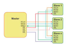
Serial Peripheral Interface (SPI) bus a synchronous serial data bus designed by Motorola. Commonly used in high speed applications such as digital audio, digital signal processing (DSP) and telecoms.
UART, TXD and RXD.
A Pulse Width Modulator (PWM).
The OS makes the hardware available to a variety of high level program languages including Python, C, Java, BASIC, Perl and Bash shell scripts.
Additional I/O pins are available by hacking.
Serial Peripheral Interface
Full duplex communication.
Higher throughput than I²C.
Complete protocol flexibility for the bits transferred.
Not limited to 8-bit words.
Arbitrary choice of message size, content, and purpose.
Extremely simple hardware interfacing.
Typically lower power requirements than I²C.
No arbitration or associated failure modes.
Slaves use the master’s clock, and don’t need precision oscillators.
Slaves don’t need a unique address — unlike I²C.
Transceivers are not needed.
Uses only four pins on IC packages, and wires in board layouts or connectors, much fewer than parallel interfaces.
At most one unique bus signal per device (chip select); all others are shared.
Signals are unidirectional allowing for easy isolation.
Not limited to any maximum clock speed, enabling potentially high throughput.
The Raspberry Pi – An Introduction and more