


A Complete 13.8 Volt, 20 Amp PSU
by Steven Goodier, G4KUB and John Goodier, G4KUC
Background and History
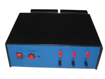 |
| PSU Front |
This article was originally published in the September 1987 issue of “Amateur Radio Magazine” and was presented in two parts. It was felt at the time that the format of the article, the art work and the way it was published never gave full justice to this project. There were many mistakes in the art work and the magazine never published a full size PCB overlays or easy to follow wiring instructions. In truth it was a waste of a “dam good” constructional project.
At the time my brother and I had built a number of power supply units but had never attempted to build anything that was capable of supplying more then around 10 amps. The most successful design of the day was the PW Marchwood by Nick Allen-Rowlandson BSc G4JET, published in Practical Wireless June and July 1983. This was a huge 30 amp design and one of the first to be published in a constructional magazine. This opened the door to the possibility of designing and building a similar unit and for the first time a 42 Amp, 16 volt transformer became available off the shelf at reasonable cost.
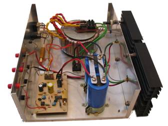 |
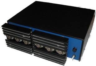
| Inside of Finished PSU |
With that in mind we set about designing a similar unit and the result was the article published in Amateur Radio Magazine. I rediscovered the original plans a few weeks ago and decided I would republish them in electronic format in a form of Internet Web pages and make this long forgotten design available again to anyone who might be interested in building a homemade, high current power supply or indeed anyone just interested in reading about and looking at the design.
We could never take much credit for the design, it’s all basic stuff taken from other circuits, reworked and made to fit our requirements. Where I think this design did differ is it was always planned that the average constructor should be able to build and get this unit working and end up with a useful high current PSU that would last many years. My unit dates back to 1987, as I write this it is now October 2007 some twenty years later. Yes, the PSU is still going strong out living my old TS440 and a TS850 plus numerous high current VHF transceivers. All the photographs you will see have been taken from the original some 20 years after it was built. I feel that is a good recommendation in itself.
I wish to dedicate this publication to Steven Goodier, G4KUB who lost his fight against cancer 14 years ago. I think he would be pleased to see this Power Supply Unit see the light of day again and I know he would take great delight in knowing that other constructors are once again enjoying building the unit as we did twenty years ago.
John Goodier G4KUC / G8VHF
Part 1
Introduction
Over the years there have been many articles in the radio/electronic journals dealing with fixed voltage high current power supplies. Most of the articles have been excellent when dealing with the theory and specifications of such units but are badly let down when describing the construction and suggesting that most of the components needed are available in the reader’s junk box. This maybe so for the minority, but not so for the majority leaving the reader wondering whether a particular component he or she may have is suitable for the circuit described.
Most readers of this magazine are only interested in a 13.8 volt, 20 amp P.S.U. which is suitable for powering the average solid state HF rig or 100 watt VHF/UHF linear. Not wanting to purchase a commercial unit which would cost about £150 I set out to build such a supply to power my TS-440S HF rig. I wanted it to incorporate the following features:-
- Capable of producing 20 Amps continuous output at a steady 13.8 volts.
- Over voltage protection.
- Under voltage protection.
- Short circuit proof.
- Current limit.
- Most of the smaller components to be mounted on a single PCB.
- All components to be available .off the shelf., including a 16.5 volt 40 Amp transformer.
I estimated that the total cost of this power supply to be in the region of about £70.00 when buying brand new components but a considerable saving can be made by purchasing most of the components from local rallies.
Circuit Diagram
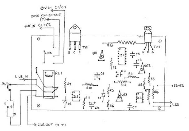
A block diagram of the full supply is shown in Figure 1 and the full circuit diagram is shown in Figure 2 and Figure 3.
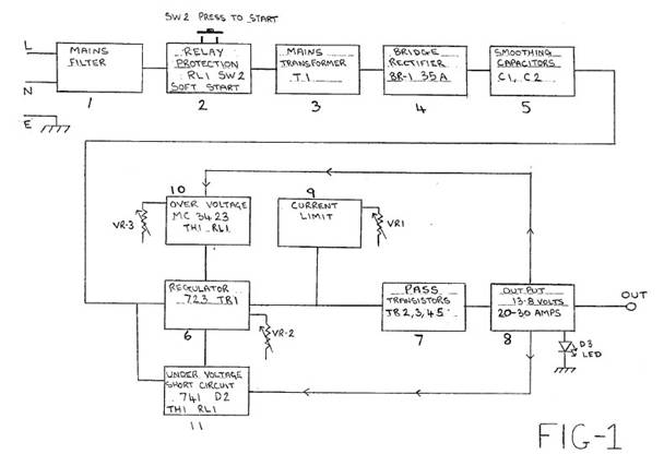 |
| Figure 1 |
 |
| Figure 2 |
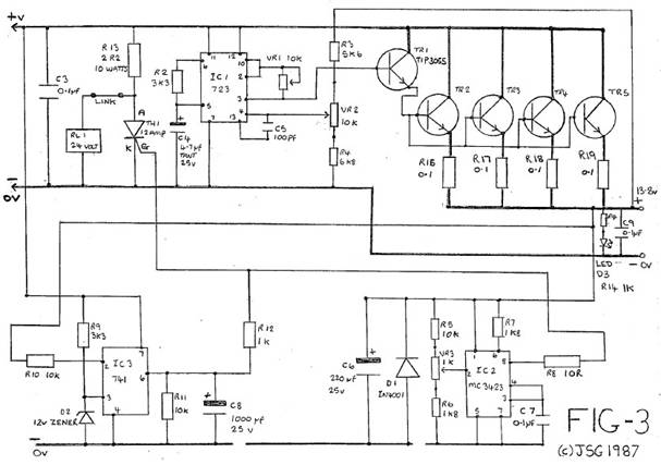 |
| Figure 3 |
The heart of the power supply is the main control board, this contains the regulator, under voltage protection, current limit, short circuit protection and the circuit breaker relay which will remove the mains supply in the event of a fault occurring. Once the main control board has been made up, it is up to the constructor how big or how small the final power supply will be. The final choice of transformer, bridge rectifier, smoothing capacitors and pass transistors will determine the final current rating of the supply. With the transformer, bridge rectifier and smoothing capacitors specified and using six pass transistors, the supply should be capable of producing 25 to 30 amps at 13.8 volts output.
What follows is a brief circuit description and some notes to help the constructor when choosing components. It will help refer to the block and circuit diagrams and each will be described in box form; also see the component notes for stock numbers, suppliers etc.
Box 1
The mains input can be taken to a 6 amp mains filter. This filter is optional and was not used in the prototype. The filter is designed to filter any interference on the main’s supply and RS type 238-536 will operate over a frequency range of 600KHz – 100MHz and provides approximately 30dB attenuation.
Box 2
Protection for the P.S.U. is provided by a relay which in the event of a fault will disconnect the mains supply. This relay must have a 24 volt coil and the recommended type is Vero 258-511956 which is rated at 16 amps at 380 volts A.C., this will also fit the PCB layout. In the event of a fault the thyristor TH-1 grounds the coil opening the relay contacts and disconnecting the mains, in turn the smoothing capacitors are discharged through R13 and TH-1. To start the supply SW-2 is pressed. This is a push to make switch and must be of a good quality type. When pressed it shorts out the relay contacts and mains voltage is allowed to flow to the mains transformer T-1 via the 50 ohm resistor R-15. The job of R-15 is to limit the in-rush of current on switch on. The in-rush of current happens because the smoothing capacitors are empty of charge and R-15 allows charging to take place slowly thus protecting the bridge rectifier BR-1.
Box 3
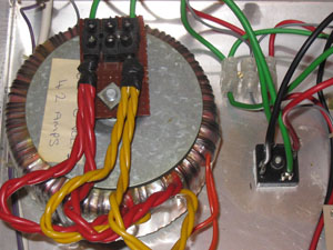
The recommended mains transformer is rated at 16.5 volts 42 amps and is of the toroidal type. It is made up of two 21 amp winding’s which must be wired together to provide 16.5 volts at 42 amps. A considerable saving can be made here by purchasing a mains transformer from the local rally. I would not recommend a secondary voltage of more than 18 volts. This is because the more the secondary voltage is the more the pass transistors will have to drop to provide the 13.8 volts needed at the output. When high current is drawn a lot more heat will have to be dissipated by each transistor if the secondary voltage is high. With the recommend transformer and four pass transistors the heatsink only runs warm to the touch when running 100 watts of SSB from my TS-440S.
Box 4 & 5
The output of the transformer is passed onto the bridge rectifier BR-1 which converts the voltage from A.C. to D.C. The rectifier can be of almost any type as long as it is rated higher then the expected current output. The prototype used a 35 amp, 200 volt bridge RS 262-523. If wished individual power diodes can be used but in either case a heatsink will be needed. The bridge rectifier can be bolted to the chassis. The output from the bridge rectifier is passed onto the main smoothing capacitors C1 and C2. A good rule of thumb here use 2000 to 3000 uF per amp, so for of 30 amp P.S.U. a value of approximately 60,000 uF should be ample.
Box 6
Voltage regulation is provided by the very popular LM723 which has appeared in many power supply designs over the years. It has a maximum input voltage of 40 volts and very few external components are needed to get the IC up and running. It is also capable of providing current limiting and the IC is supplied in a 14 pin DIL package. The 723 is only capable of supplying about 150 mA, so a pre-driver transistor is needed to ensure that there is enough current gain to drive the pass transistors. This is taken care of by TR1 which is a TIP3055. The output voltage is set by the resistor combination R3, R4 and VR-2. R3 is connected to the output to sense any volts drop and VR-2 is used to set the output voltage, the output voltage swing should be in the region of 12 to 15 volts.
Box 7
All the current provided by the power supply is handled by the pass transistors TR-2,3,4 and 5, although in practice for a 25 to 30 amp supply six transistors are recommended. It is up to the constructor how many transistors are used and in turn this depends on the output current required. For example in a 10 amp supply only two devices need be used. The transistors used are 2N3055s which can handle a maximum current of 15 amps each. The bases and collectors of each transistor are wired together and each emitter has in series with it a 0.1 ohm, 3 watt resistor to ensure current sharing. The devices need to be bolted to hefty heatsinks to ensure cool running, but it must be said when drawing 20 amps or more continuously they will run fairly hot. The 0.1 ohm resistors are made up from two 0.22 ohm, 3 watt wirewound resistors wired in parallel.
Box 8
The outputs from the pass transistors are taken to the output terminals on the front or back panels of the case. The outputs can be taken to RED and BLACK terminal post and Maplin or RS components both stock suitable types. A red “ON” LED indicator is also wired to the front panel and this is taken from the main PCB. There is also a 0.1 uF capacitor wired across the output. Sense wires are also taken back to the over and under voltage circuits.
Box 9
Current limiting is controlled by VR-1 and this facility is offered by the LM723 voltage regulator IC. Current limiting sets the maximum amount of current that the power supply will deliver and protects the supply from excessive currents.
Box 10
If there is a short circuit between emitter and collector on any of the pass transistors then the un-regulated supply will appear at the output terminals. Therefore it is important we have some form of over-voltage protection. This is provided by IC-2 an MC3423 over-voltage crowbar protector (RS 307-890). Voltage is fed back from the output to pin 2 of IC-2 via the resistor network R5, R6, and VR-3. The setting of VR-3 determines the firing voltage usually 15 volts for a 13.8 volt power supply. To prevent false tripping the MC3423 has a programmable delay feature. C7 determines the minimum duration of the over-voltage condition which will trip the protector. With the value in circuit this will be about 1mS. A value of 0.01uF will give a delay of about 0.1mS. When voltage rises above the pre-set level pin 8 goes high and fires the thyristor TH-1 which in turn grounds the relay coil, removes the mains supply and C1 and C2 which are rapidly discharged via R13.
Box 11
An under-voltage circuit as been added to detect any drop in output voltage which could indicate a fault in either the power supply or the supplied equipment. It will also detect a short circuit on the output and in turn switch the supply off. The detector is built around a 741 op-amp IC-3. A reference voltage is generated via R9 and D2 and applied to pin 3 the non-inverting input. The output voltage is sampled by R10 and applied to pin 2. When the voltage drops below the reference voltage set by D2 pin 6 goes high firing the thyristor TH-1.
Component Notes
Most components are easily obtained and to help with some I have given the RS/Electromail, Maplin Electronics or the Verospeed stock number.
The transformer can be obtained from; Jaytee Electronic Services, 143, Reculver Road, Beltinge, Herne Bay, Kent, CT6 6PL. (tel: 0227 375254).
The following notes maybe of some help.
 |
| Smoothing Capacitors |
Resistors: All resistors are 1/4 watt 5% apart from R13, R15 and R16 through to R19. R13 is an aluminum clad 2R2, 25 watt resistor (Vero 90-36606E). R15 is also aluminum clad but rated at 50R, 50 Watts (Vero 90-36678F). The current sharing resistors R16, 17, 18, 19 are made up from paralleled pairs consisting of two 0.22R, 2.5 or 3 watt resistors available from Maplin or Verospeed.
Capacitors: All the capacitors are of common type. Smoothing capacitors can be obtained from the local rally and failing that RS can supply 33,000uF at 40 volts RS 105-420. It must be said that the final value of C1 and C2 will depend on the final current rating of the supply.
Semiconductors: There should be no problem getting hold of any of the semiconductors for the project. Shop around for the MC3423 over-voltage chip as this can range in price. 12 and 13 amp thyristors are available from both RS and Maplin, Vero also stock a suitable item.
 |
| Mains Transformer |
Miscellaneous: The 6 amp mains filter is an optional extra and was never fitted to the prototype. Make sure both switches are of a good quality. The relay RL1 must have a 24 volt coil, I used a 16 amp S.P.C.O. which is available from Vero but RS stock a 10 amp relay RS 347-836. Most PCB type relays of the same size should fit the board and the PCB layout as taken into consideration the possible different pole arrangements.
Mains Transformer: The mains transformer Tl is available from Jaytee Electronics Services, stock number 9T845 “Marchwood” transformer. The solder eyelets and push on connectors are available from RS see page 150 of the Electromail catalogue. They are used to connect wires between the transformer, bridge rectifier and smoothing capacitors. The PCB is homemade and an easy way to make this will be described later on.
References
- Fixed Voltage High Current Power Supplies by Roger Alban GW3SPA. Amateur Radio August 1986.
- Power Supplies On A Shoe String by John Case GW4HWR. Radio Communication July and August 1986.
- Marchwood Power Supply Unit by Nick Allen-Rowlandson BSc G4JET. Practical Wireless June and July 1983.
- RS Data Sheet 1303 July 1983 L723 voltage regulator.
- RS Data Sheet 3396 March 1985 MC3423 overvoltage crowbar protector.
Components List
See also the Component Notes above
Resistors
| Reference | Value | Reference | Value |
|---|---|---|---|
| R1 | 10K | R9 | 3K3 |
| R2 | 3K3 | R10 | 10K |
| R3 | 5K6 | R11 | 10K |
| R4 | 6K8 | R12 | 1K |
| R5 | 10K | R13 | 2R2 25 Watts |
| R6 | 1K8 | R14 | 1K |
| R7 | 1K8 | R15 | 50R 50 Watts |
| R8 | 10R | R16 etc. | 0.1R 3 Watts |
Capacitors
| Reference | Value | Reference | Value |
|---|---|---|---|
| C1 | 33,000uF Elec 40 Volt | C6 | 220uF Elec 25 Volt Radial |
| C2 | 33,000uF Elec 40 Volt | C7 | 0.1uF Disc |
| C3 | 0.1uF Disc | C8 | 1,000uF Elec 25 Volt Radial |
| C4 | 4.7uF Tant 25 Volt | C9 | 0.1uF Disc |
| C5 | 100pF Ceramic |
Semiconductors
| Reference | Value | ||
|---|---|---|---|
| IC1 | LM724 Voltage Regulator 14 Pin DIL | ||
| IC2 | MC3423 Overvoltage Crowbar Protector (RS 307-890) | ||
| IC3 | 741 Op-Amp | ||
| TR1 | TIP3055 | ||
| TR2,3,4,5 etc. | 2N3055 | ||
| D1 | 1N4001 | ||
| D2 | 12 Volt 400 mW Zener | ||
| LED | Red and Holder | ||
| BR1 | 35 Amp High Power Bridge Rectifier | ||
| TH1 | 12 Amp Thyristor (C1260 or BT152) or Similar | ||
Miscellaneous
| Item |
|---|
| 6 Amp Mains Filter (OPTIONAL) |
| SW1 – Mains ON/OFF Switch Rocker or Toggle |
| SW2 – Good Quality PUSH TO MAKE |
| 5 Amp Mains Fuse & Holder |
| RL1 – 24 Volt Coil Single Pole changover Relay |
| T1 – 16.5 Volt 42 Amps Mains Transformer |
| IC Holders 2 X 8 Pin F 1 X 14 Pin DIL |
| Heatsinks 2 X 1.1 deg C/W 152mm X 130mm X 32mm Heatsink to suit TIP3055 |
| Semiconductor Mounting Kits TO-3 |
| High Current Wire: RED and BLACK |
| Terminal Post |
| Terminal Block (12 and 30 Amp) |
| Push on solder tags to suit bridge rectifier |
| Solder eyelets to suit smoothing capacitors Mains Cable 6 Amp |
| Printed circuit board, PCB Pen and etch Case, Nuts, Bolts, Wire etc. |
Part 2
Construction
In part-1 we outlined the basic needs of an high current power supply and dealt with the protection circuits needed for safe operation. In part-2 we will deal with the construction of the unit itself including PCB layout, wiring diagrams and testing.
The Printed Circuit Board
 |
| Figure 4 (top) |
Most of the smaller components are mounted on a single sided printed circuit board. I have had little experience of making PCBs, but during the construction of the prototype I developed a simple and sure method of producing reasonable quality home made PCBs. Figure 4 (top) shows the component side of the PCB and the position of each component, Figure 4 (bottom) shows the copper track pattern.
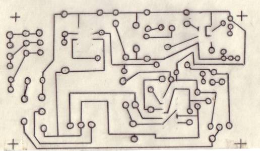 |
| Figure 4 (bottom) |
The problem most people have is getting the track pattern off the paper and onto the board and still maintaining a reasonable amount of accuracy. To make the PCB you will need a piece of single sided board 135mm long X 75mm wide, tracing paper, PCB pen and etch. The board was made using the following method:
- Make a tracing of the pattern and where a hole is to be drilled on each pad mark with a pencil dot. Be careful to mark the Positions of the ICs, preset resistors and relay accurately. When finished turn the tracing paper over and re-draw the pattern in thick pencil.
- Clean the PCB with wire wool and then wash it in hot soapy water. Fix the tracing onto the board using sticky tape at the top only, so you are able to lift the tracing up like a flap.
- The next job is to mark onto the board the position of each hole to be drilled, this is done using a scribe or sharp pointed instrument. With the tracing flat onto the board place the scribe onto the pencil dot on each pad and gently tap it with a small hammer, this will make an indent on the copper board and will clearly mark each drilling position.
- With a blunt instrument rub over all the pencil lines, this should reproduce a faint image onto the copper board. Every so often just lift the tracing paper up and check all is going well. It may be possible to place between the board and the tracing paper a piece of carbon-less paper and this should produce a much better image.
- When satisfied remove the tracing paper and start to re-draw the pattern onto the board with a PCB pen. Be careful when drawing the IC pads and thicken up the lines as shown on the layout. A Staedtler Lumocolor 318 Permanent PCB pen sold by Maplin Electronics was used on the prototype board but other types should work just as well.
- When the ink has dried etch the board following the instructions supplied with the acid. The acid works from the edge inwards and I would advise you to apply more ink to the tracks at the edge of board than those towards the centre. You will know when the acid is working as the un-covered copper starts to turn pink and slowly dissolves. When the board is etched clean off the ink with wire wool and drill the holes.
Construction can be split up into four parts:
- Wiring and testing of the transformer, rectifier and smoothing capacitors.
- Construction and testing of the PCB.
- Wiring of the pass transistor’s to the heatsinks.
- Final wiring and testing.
The first job is to layout the main components in the case. Mark and drill all fixing points to the base, front and back panels, see Figure 6 for layout details. The mains filter, if used, is a surface mounting type and room can be made for this at the mains input. The heatsinks are held in place on the back panel with long bolts and are allowed to stand off 40mm or so, a large hole should be drilled in the back panel to allow wiring to pass through from the pass transistors. The heatsinks will overhang the case on either side. When the holes have been drilled and the case painted and labeled bolt into position the following components:- T1, BR1, C1, C2, R15, F1, and the two terminal blocks. To the front panel secure SW1, SW2, LP1, the output terminals and the LED. The PCB and heatsinks will be added later.
Transformer Wiring and Testing
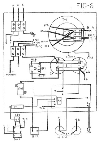 |
| Figure 6 |
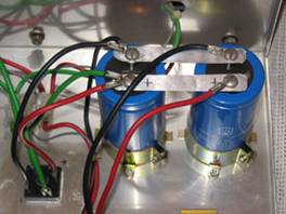
We will start by wiring the secondary of the transformer, bridge rectifier and smoothing capacitors, but we will not be wiring the primary side yet. The secondary of the transformer used has two tappings which must be wired together to produce 16.5 volts at 42 amps. I used a piece of plane veroboard and bolted to it a 30 amp terminal block which was then fixed to the mounting bolt of the transformer. I then wired to it the output of the transformer as shown in Figure 6. Two heavy duty wires are then taken to the A.C. side of the bridge rectifier BR1, these are then fixed in place with push on connectors. C1 and C2 must be wired in parallel and this can be achieved by strapping the terminals of the capacitors together. I used two strips of aluminium which are then bolted to the capacitor terminals; MAKE SURE you bolt POSITIVE to POSITIVE and NEGATIVE to NEGATIVE.
The positive and negative sides of BR1 can be wired to the respective sides of the capacitors. I used solder eyelets to make the connections to the capacitors and push on connectors for BR1. Remember to connect R1 across C1 and C2. All the wiring for this section is shown in Figure 6. That completes the wiring of the first section and it can now be tested.
Testing the First Stage
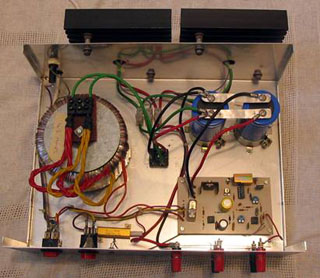 |
| Inside the PSU |
To test this section you will have to temporarily connect 240v A.C. to the primary side of T1. First connect a voltmeter across C1 and C2, turn the power on and check the reading on the meter, this should read about 24 to 26 volts D.C. If all is well then switch off and allow the smoothing capacitor’s to discharge through R1. NEVER be tempted to discharge these capacitors by placing a screw driver across them. A word of warning, you are now dealing with 240v A.C. which if touched could result in a very nasty accident. If in doubt get an experienced constructor to check your work.
PCB Construction and Testing
With the first part wired and tested we can now move onto the construction of the PCB. Figure 4 (TOP) shows the component overlay of the board. Mount and solder all the components as shown. Take care to mount the diodes, electrolytic capacitors and the semiconductors the correct way round. You may have to enlarge the mounting holes to take RL1. R13 is stood off the board and is held in place by thick copper wire. TR1 is best mounted in place with the heatsink already attached.
Testing the Control Board
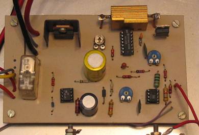 |
| PSU Control Board |
It is possible to test the board before finally wiring it into place. To test the board you will have to supply it with about 20 to 25 volts D.C. BUT UNDER NO CIRCUMSTANCES must you use the section already wired to supply this voltage. When testing the board you will simulate several fault conditions and at the moment there is no way of disconnecting the mains when a fault occurs; failure to remove the supply will result in the possible destruction of R13 and TH1. I used a 0 to 30 volt, 1.5 amp variable power supply.
First set the preset resistors as follows, VR1 centre, VR2 centre and VR3 fully anti-clockwise. Next connect a wire between the sense output and the emitter of TR1. Bring in the supply wires from your external variable PSU and wire the positive to the “+” volts in and the negative to “0 volts.”
Turn the supply voltage on and if possible set the output to about 23 volts. The on board relay should “pull-in” and if you check the output voltage at the emitter of TR1 it should read 13 to 15 volts. Rotating VR2 should adjust the output voltage. To test the under voltage stage monitor the output and adjust VR2, when the output voltage reaches about 12 volts the relay should “dropout”. Under a fault condition the positive input voltage is almost shorted to ground via R13 and TH1 so make sure your variable supply is short circuit proof. Switch off and reset VR2 to about centre.
To test the over voltage stage set the output voltage to 15 volts using VR2, then adjust VR3 until the relay “dropsout”. Switch off your supply and re-adjust VR2 to its centre position again. Switch back on and monitor the output, start to increase the output voltage via VR2, when it reaches about 15 volts the relay should “dropout” as the over voltage protection trips in. Switch off and re-adjust VR2 to its centre position. Remove the link between the sense and TR1 emitter. This completes the testing of the PCB.
The relay specified has a coil voltage of 24 volts but under operating conditions it has been found that a voltage as little as 13 volts will “pull” the relay in. The operating voltage at which the relay will open or close can be increased by placing a resistor in line with the coil. The board as a link close to the relay and this can be replaced with a resistor, the value of which can be between 100 and 560 ohms. A good starting point is about 220 ohms. You may not feel that this resistor is necessary, but if you think that the relay is operating in a sluggish manner then add it. If the value is too high then the relay will not pull in when SW2 is pressed.
Pass Transistors
Figure 5 shows the pass transistors mounted on the heatsinks, these must be mounted using TO-3 mounting kits. The amount needed depends on the final rating of the supply and the diagram shows the six transistors needed for a 30 to 35 amp supply. Start by marking the position of each transistor on the heatsink, you can use the mounting kit insulator as a template. Drill all mounting holes and bolt all transistors to the heatsinks using the TO-3 kits. Using an ohms meter check there are no short circuits between the case of each transistor and the heatsink.
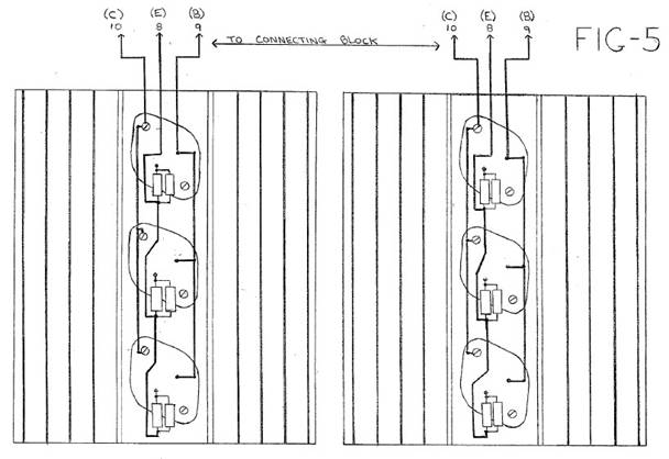 |
| Figure 5 |
 |
| Heatsink with Pass Transistors |
Next wire the transistors as shown in Figure 5. As already stated the 0.1 ohm current sharing resistors are made up of 0.22 ohm paralleled pairs and this is clearly shown in Figure 6. Use heavy current wire for the collector and emitter wiring. All wiring is then taken into the case and coupled together via a 30 amp terminal block see Figure 6.
Main Wiring
You are now ready to couple together all the parts of the power supply to make one complete unit, the main wiring diagram is shown in Figure 6. A good idea here is to start to use colour coded wire to identify the voltage rails, perhaps ORANGE for the un-regulated supply, RED for the 13.8 volt regulated output and BLACK for negative rail. Suitable high current wire can be obtained from Maplin Electronics, see components list. Also use colour coded wire for the mains supply i.e. BROWN live, BLUE neutral and GREEN/YELLOW for the earth.
The first stage of the supply should already be wired and working, so it is just a matter of wiring the mains input, PCB and front and back panels. Follow the diagram carefully and double check all wiring. Put insulated sleeving on both sides of R15 and F1. If you are in doubt get a friend with a little more experience to check your work.
Final Testing and Setting Up
Give all wiring a final check and if satisfied you are now ready to test the full supply. Fit the mains plug with a 5 to 7 amp fuse. If the PCB has not already been tested then set the pre-set resistors to the following positions:- VR1 centre, VR2 centre and VR3 fully anti-clockwise. Connect a voltmeter to the output, plug in and switch on. Pressing SW2 should cause the relay to pull in and the front panel LED to light. If the relay pulls in and quickly drops out again then this could indicate that the output voltage is below 12 volts and firing the under voltage circuit. If this happens then turn VR2 up slightly. If all is well then the output voltage should read between 13 and 15 volts. To test the supply the procedure is similar to that all ready described in “Testing the PCB” but I will go through it again in a little more detail.
Under Voltage: To test the under voltage stage monitor the output and adjust VR2, when the output voltage reaches about 12 volts the relay should drop out and the mains supply switched off. Re-adjust VR2 to its previous position and re-start the supply by pressing SW2.
Over Voltage: To set the over voltage trip the output voltage needs to be increased to about 15 volts or to the level at which the trip is needed. For a 13.8 volt supply this is usually about 15 volts. First make sure VR3 is fully anticlockwise and then adjust the output voltage to the required trip level, say 15 volts. Adjust VR3 until the relay “drops-out” and the supply is switched off. Re-adjust VR2 to about its normal operating position and restart the supply by pressing SW2. Monitor the output and start to increase the output voltage again, at about 15 volts the over voltage should trip and the supply switched off.
The under and over voltage can be checked again if wished by simply turning VR2 down to about 12 volts or up to 15 volts. At each level the protection circuits should trip and turn the power supply off. Don’t forget to re-set VR2 to its normal position before re-starting the supply again. Finally set the output voltage to the required level ie 13.8 volts.
Current Limit: The supply can now be tested on load and the current limit set. To do this you will have to find a resistive load which can draw the required current. To do this I used a 0.68 ohm 50 watt resistor and water cooled it in a bowl of cold water! Using ohms law a 0.68 ohm resistor will draw about 20 amps and a 0.47 ohm will draw about 25 amps when supplied with 13.8 volts. If you are going to set the current limit properly you will need a current meter that can measure at least 30 amps.
Turn VR1 fully clockwise. Switch the power supply on and then connect the meter and load to the output, make sure that the load is submerged in a bowl of cold water before starting. When the supply is drawing full load adjust VR1 until the output current drops back to about 20 amps. A suitable current meter was not available when setting up the prototype so I placed a voltmeter across the output and on full load I set VR1 so that the output voltage fell back to 13.5 volts. If you set the output to fall below 12 volts this will turn the supply off.
Short Circuit: To test the short circuit protection you will have to place a short across the output terminals. Momentarily shorting the output should have no effect but leaving the short on for more then half a second should cause the supply to close down.
The power supply is now set-up and ready for use. Before putting it into full operation leave the supply switched on for about two hours and every so often draw about 20 amps from it using the 0.68 ohm resistor. This should show up any faults before connecting it to the main equipment. The equipment powered must have its own in-line fuse as the power supply has no internal fuse of its own.
Modifications
A number of modifications have been made to the original design and these are listed below.
- The values of the resistor combination R3, RV2 and R4 can be changed to provide a better output voltage swing. Replacing them for the following values will produce an output voltage swing of approximately 12.5 to 14.5 volts.R3 – 4K7
RV2 – 1K
R4 – 5K6Note: If you decide to use the new values then you won’t be able to drop the output voltage below 12 volts to test the under voltages protection circuit. To test this stage simply switch the supply on and monitor the output with a volt meter. Switch off, and after a few seconds the output voltage will start to fall, when it reaches about 12 volts the relay should trip and to the output will quickly drop to zero. Because you can’t increase the output above 15 volts the overvoltage stage will have to be setup at 14 to 14.5 volts. - The current limit pre-set resistor RV1 should be changed for a value of 470R or 100R. This makes setting the current limit a lot easier.
Conclusion
The prototype has been in daily use now for about six months and has been faultless in operation. The prototype only used four pass transistors and it easily powers my TS-440S with 100 watts output on FM. When finished and working the power supply is a worth while and very useful addition to the radio shack. The main control board is very versatile and could be adapted for other uses. By changing the resistor network 83, VR2 and 84 a varity of output voltages could be obtained.